How to Calculate Electric Tricycle Rear Axle Gear Ratio
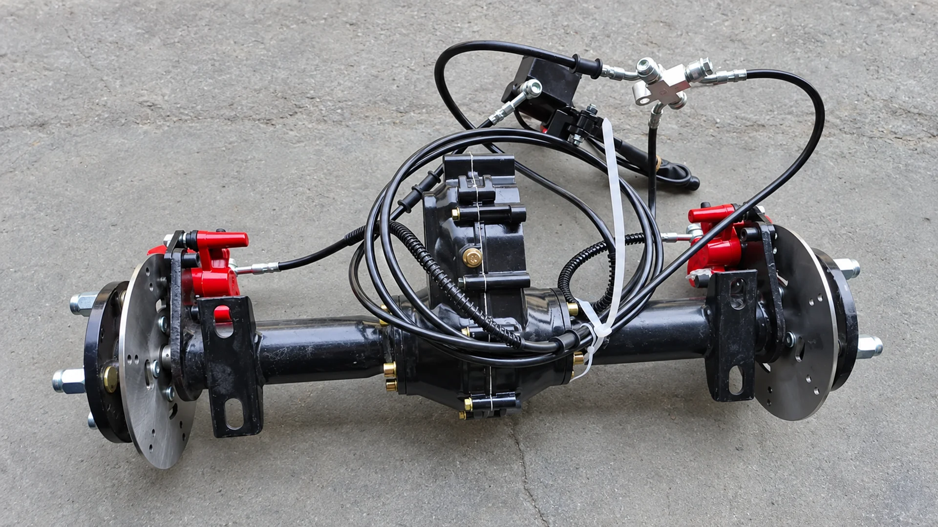
Calculate an electric tricycle rear axle gear ratio by dividing the speed of the defined input shaft by the speed of the defined output. For a simple gear pair, divide the driven gear’s tooth count by the driving gear’s tooth count. When several reduction stages lie between the motor and the wheels, multiply their ratios to obtain the total reduction.
To turn that ratio into vehicle speed, you also need the motor’s mechanical rpm and the tires’ effective rolling circumference. The method below applies to a drivetrain in which a motor drives the rear wheels through reduction gearing and an axle. It does not assume that every electric tricycle uses this arrangement.
Define Which Gear Ratio You Are Calculating
A reduction ratio compares two named points in the drivetrain. Using rotational-speed magnitudes:
Reduction ratio, i = input rpm ÷ output rpm
A 10:1 reduction therefore means that the input makes ten revolutions for each output revolution. At a given input speed, a larger numerical reduction produces a lower output speed. This input–output relationship is described in maxon’s gear technical notes. maxongroup.com
The term “rear axle ratio” can refer to a reduction within the axle assembly. It may exclude a separate upstream gearbox or a reduction at the wheels. For vehicle-speed calculations, the relevant quantity is the total motor-to-wheel reduction ratio.
| Ratio description | Required boundary |
| Single-stage ratio | Input and output of one identified reduction stage |
| Gearbox ratio | Gearbox input and output in the specified gear position |
| Rear axle ratio | The supplier’s specified axle input and output points |
| Total reduction ratio | Motor shaft to driven wheels, including every intervening reduction |
A gearbox reduces speed through its gear arrangement. A differential allows the driven wheels to turn at different speeds. Those functions can be combined in an assembly, but the terms do not identify the same mechanical relationship. Establish the actual transmission path before selecting numbers for a calculation.
Calculate the Ratio from Gear Teeth or Shaft Speeds
Use Confirmed Driving and Driven Gear Teeth
For a simple pair of meshing gears:
i = driven gear teeth ÷ driving gear teeth
Consider a hypothetical 20-tooth driving gear engaging a 60-tooth driven gear:
i = 60 ÷ 20 = 3:1
The driving gear turns three times for one revolution of the driven gear. Dana/Spicer uses the corresponding driven-to-driving tooth-count relationship in its ring-and-pinion ratio calculation. spicerparts.com
The tooth counts must belong to a confirmed gear pair. A tooth count in a half-shaft description may refer to splines used for a mechanical connection. It does not establish a reduction ratio with another separately listed part. Planetary arrangements also require their correct kinematic relationship; dividing two convenient tooth counts is insufficient.
The speed-ratio method gives the same result when the input and output are identified correctly: 3000 rpm at the input and 1000 rpm at the output produce a 3:1 ratio. Both values must describe the same operating condition and transmission path.
Multiply Consecutive Reduction Stages
If the hypothetical 3:1 stage is followed by a separate 4:1 reduction, the total ratio is:
i_total = 3 × 4 = 12:1
At 3000 motor rpm, the first stage reduces speed to 1000 rpm and the second to 250 rpm. Multiplying the ratios accounts for both stages. Using only the first stage would give the wrong wheel-speed prediction.
Account for Differential Wheel Speeds
For an ideal symmetrical open differential, with left and right shaft speeds expressed in a common forward direction:
Carrier rpm = (left shaft rpm + right shaft rpm) ÷ 2
This average-speed relationship follows from the fundamental constraints in MathWorks’ differential model. With no additional wheel-end reduction, both wheels turning at 250 rpm correspond to a carrier speed of 250 rpm. If the two wheel speeds differ, one wheel alone does not represent that average. MATLAB
Consequently, an arbitrary free-spinning wheel speed cannot be treated as the axle output speed when calculating a ratio. Apply this relationship only after the differential type and measurement points have been established.
Convert Motor RPM and Tire Circumference into Road Speed
Calculate Wheel RPM and Theoretical Vehicle Speed
For straight-line travel with both driven wheels at the same speed, no tire slip and every reduction stage included:
Wheel rpm = motor rpm ÷ total reduction ratio
Each wheel revolution advances the vehicle by its effective rolling circumference. Converting metres per minute into kilometres per hour gives:
Theoretical speed (km/h) = motor rpm × C × 60 ÷ (1000 × i_total)
Here, C is effective tire rolling circumference in metres per revolution and i_total is the motor-to-wheel reduction ratio. Use mechanical motor rpm. A controller display’s electrical rpm requires the appropriate motor-specific conversion before it can be used in this formula.
Dana/Spicer’s transmission calculator similarly relates shaft speed, transmission ratios and tire dimensions, while distinguishing mathematical calculation from vehicle application suitability. Spicer Parts
For a worked example, assume:
- Motor operating speed: 3000 rpm.
- Effective rolling circumference: 1.50 m per revolution.
- Total reduction: 10:1.
The calculation is:
Wheel speed = 3000 ÷ 10 = 300 rpm
Vehicle speed = 300 × 1.50 × 60 ÷ 1000 = 27 km/h, approximately 16.8 mph.
Using the same motor speed and tires with a 12:1 total reduction gives 250 wheel rpm and 22.5 km/h, approximately 14.0 mph. These are hypothetical calculation inputs and results, not specifications for an ECOGO product.
| Hypothetical total reduction | Wheel speed at 3000 motor rpm | Theoretical road speed with C = 1.50 m |
| 10:01 | 300 rpm | 27.0 km/h / 16.8 mph |
| 12:01 | 250 rpm | 22.5 km/h / 14.0 mph |
For an ideal circular wheel, circumference can be approximated as π × diameter. In an actual vehicle calculation, use effective rolling circumference or the tire supplier’s applicable revolutions-per-distance data. Wheel-rim diameter is not tire rolling diameter, and a nominal tire designation alone may not supply the required circumference.
Work Backward from a Target Speed
Rearranging the same equation gives a candidate total ratio:
i_total = motor rpm × C × 60 ÷ (1000 × target speed in km/h)
With the same assumed 3000 rpm and 1.50 m circumference, a target of 25 km/h gives:
i_total = 3000 × 1.50 × 60 ÷ (1000 × 25) = 10.8:1
This is a calculated candidate. It does not establish that a 10.8:1 assembly is available, that the motor can sustain 3000 rpm under the required load, or that the vehicle will reach that speed.
Transmission efficiency is not multiplied into this fixed-ratio speed equation. It affects the power required and torque available. If losses prevent the motor from sustaining the assumed rpm, use the achievable rpm to recalculate road speed.
Check Torque and Operating Limits Before Choosing the Ratio
Calculate Total Drive Torque on a Consistent Basis
For steady driving, with both axle outputs at the same speed and no further reduction between those outputs and the wheels, the total motor-to-wheel ratio can be used in the following torque calculation:
Total axle output torque ≈ motor torque × i_total × overall transmission efficiency
The reduction-and-efficiency relationship is given in maxon’s gear notes. Here, “total axle output torque” means the combined torque at the two driven outputs. It does not mean that each wheel receives that full value. maxongroup.com
Extend the previous hypothetical example by assuming 5 N·m of motor torque at 3000 rpm and 0.90 overall transmission efficiency for both ratios:
| Hypothetical total reduction | Combined axle output torque | Theoretical road speed from the previous example |
| 10:01 | 5 × 10 × 0.90 = 45 N·m | 27.0 km/h |
| 12:01 | 5 × 12 × 0.90 = 54 N·m | 22.5 km/h |
The larger reduction produces more output torque at a lower output speed for the same motor operating point. It does not create additional power. The assumed 90% efficiency is only an input to this example; actual efficiency must come from applicable data or measurement.
Separate the Calculation from Vehicle Performance
Calculated output torque is not an axle’s allowable torque rating. Gear, shaft and assembly limits still apply. Similarly, axle torque is not a payload rating: force at the ground also depends on tire size and available adhesion, while the vehicle must overcome its operating resistance.
Before selecting a ratio, check whether the motor can sustain the required speed and torque with the proposed battery voltage, controller limits and thermal conditions. Replacing loaded motor-speed data with a no-load rpm value can overstate attainable road speed.
A custom gear ratio for an electric tricycle differential axle should therefore be evaluated against a defined operating point. Ratio calculations establish the relationship between speeds and torques; they do not independently establish payload, hill-climbing capability or range.
Confirm the Actual Ratio and Axle Configuration Before Ordering
ECOGO’s rear axle and drivetrain range includes an electric tricycle gearbox assembly and an integrated disc brake rear axle. Their public listings do not provide an actual ratio and complete operating ratings for the calculations above. A ratio must be confirmed for the specific assembly being considered. Ecogo
For a useful technical comparison, obtain:
- The exact assembly and transmission path: identify the motor input, each reduction stage, the differential and any wheel-end reduction.
- The actual ratio: state its input and output points and the applicable gear position, if relevant.
- The operating limits: obtain permitted input speed and continuous or temporary torque limits with their conditions.
- The vehicle calculation inputs: use the intended tires’ rolling data and a realistic loaded motor operating point.
- The installation match: verify the mounting and brake interfaces for the selected rear axle assembly.
To confirm the axle ratio and configuration with ECOGO, provide the target operating speed, tire rolling data, motor information and required duty. Those inputs allow a proposed ratio to be evaluated against the actual product, rather than treating a mathematical result as a ready-made specification.