How to Choose Controller Wattage for an Electric Tricycle
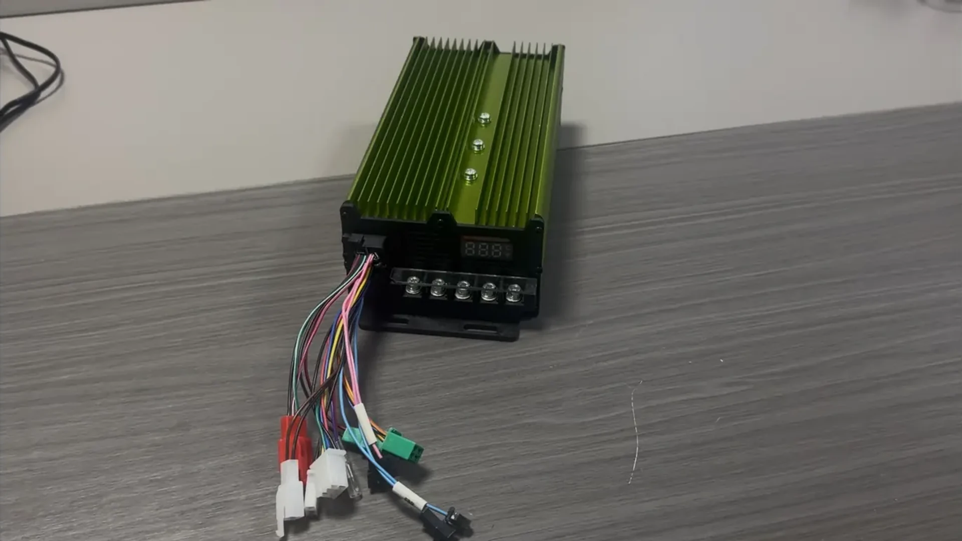
To choose controller wattage for an electric tricycle, start with the motor’s documented rating and the controller manufacturer’s stated motor compatibility. Then check the battery voltage range, battery and motor current limits, continuous operating conditions, and control interfaces. A wattage label helps identify candidates; these additional checks determine whether a candidate suits the vehicle.
This matters when sourcing a replacement controller or specifying a drivetrain for a cargo tricycle or e-rickshaw. Two controllers carrying the same wattage label may have different current limits, cooling requirements, or signal connections. Likewise, a higher advertised wattage does not establish compatibility with a particular motor.
What Does a Controller’s Wattage Rating Actually Mean?
Rated Motor Power, Electrical Input and Shaft Output
Three power values can appear in a drivetrain discussion:
- Listed motor power: the motor rating or compatibility range identified by the supplier.
- Controller DC input power: electrical power entering the controller from the battery.
- Motor shaft power: mechanical power delivered by the motor after controller and motor losses.
These values describe different points in the system. A product field called “Rated Motor Power” should be read as the stated motor power reference, unless the manufacturer provides a more specific definition. It does not, by itself, establish continuous controller input power or measured shaft output. The distinction between electrical input, electrical motor power and conversion losses is explained in maxon’s controller documentation. maxon Support
Reading Actual Controller Specifications
Two controller listings on the ECOGO website illustrate why the field names matter:
| Published field | 1000–1500W 24-MOSFET controller | 1500–3000W 36-MOSFET controller |
| Rated Motor Power | 1000–1500 W | 1500–3000 W |
| MOSFET count | 24 | 36 |
| Output Voltage | 48 V / 60 V / 72 V | 48 V / 60 V / 72 V |
| Output Current | 50–60 A | 85–100 A |
The pages do not define whether “Output Current” means battery current or motor phase current, or whether it is continuous or short-duration current. Multiplying one of these figures by a listed voltage would therefore assign a power rating that the published information does not establish. Ecogo
For a motor rated at 1500 W, both listed motor power ranges include that figure. This creates a shortlist, not a completed match: the current definitions, voltage configuration, motor control requirements and operating duty still decide suitability.
Match the Battery Voltage Window Before Comparing Power
A battery’s nominal voltage is a system label. Its voltage changes with charge level and operating load. The controller must accommodate the actual supply conditions, including the fully charged battery and the lower voltage encountered during operation. maxon’s voltage guidance explicitly distinguishes these upper and lower supply constraints. maxon Support
Compare three items:
- The battery data: nominal voltage, maximum charged voltage and expected voltage under load.
- The controller data: permitted operating range, absolute maximum rating and configured voltage protection limits.
- The required motor operating point: the speed and torque the drive must sustain within that supply range.
An absolute maximum is a limit, not a normal operating target. A nominally matching battery and controller still need an operating range that suits the vehicle.
The ECOGO listings above show 48 V, 60 V and 72 V. That list alone does not establish that every delivered unit automatically supports all three systems. Confirm the voltage version or configuration supplied for the order, including its protection settings.
Separate Battery Current from Motor Phase Current
Estimate Input Power at the Battery Connection
During motoring, battery-side current is drawn through the controller’s DC supply connection, while motor phase current flows in the windings. A PWM power stage changes the effective voltage applied to the motor. Motor-side current can therefore exceed average battery current without creating additional power; the readings describe different sides of the conversion. Their relationship depends on operating conditions and how current is measured. maxon Support
For approximately steady DC voltage and current:
Controller input power ≈ DC bus voltage × battery current
Consider a hypothetical measurement of 60 V at the controller input under load and 30 A of battery current:
60 V × 30 A = 1800 W, or approximately 1.8 kW of electrical input.
This is neither a measurement of shaft power nor a continuous rating inferred from a product name. If the same system has a separately specified 60 A phase-current value, multiplying 60 V by that value does not establish 3.6 kW of input or shaft power.
Where voltage and current fluctuate substantially, accurate average power requires averaging their instantaneous product over the same period. Multiplying unrelated readings, or averages from different operating conditions, can give a misleading result.
Compare Current Limits on the Same Basis
| Current specification | What it helps assess | Definition needed |
| Battery-side current | Compatibility with the battery and battery management system (BMS) | Continuous limit, temporary limit and permitted duration |
| Motor phase current | Compatibility with the motor’s electrical and thermal requirements | Measurement convention, continuous limit and temporary limit |
Current magnitude and operating duration are separate questions. “Peak” can mean the peak of an electrical waveform or a temporary overload rating. RMS current is another measurement convention; it is not a synonym for continuous current.
Kelly’s KLS-H manual provides an example of a controller family with separate battery-current and motor-current settings. For an ECOGO order, obtain the definitions for the actual model before using its published current figure to select a BMS or judge motor compatibility. media.kellycontroller.com
Check Continuous Duty, Peak Duration and Cooling
A temporary current rating only becomes useful when its allowed duration and thermal conditions are known. Continuous capability also depends on the specified installation and cooling arrangement. Kelly’s KLS-H documentation separates continuous and peak ratings and gives heatsink installation requirements, illustrating why these conditions belong alongside the current figures. media.kellycontroller.com
For a working tricycle, compare the required current over the operating cycle with the documented limits. A brief acceleration, repeated loaded starts and a sustained climb place different demands on the drive. Completing one acceleration does not demonstrate that the same output can be maintained repeatedly or continuously.
Low-speed, high-torque operation deserves attention. Shaft power depends on both torque and speed, while motor current can remain substantial at low speed. A modest mechanical power figure therefore does not establish a low thermal burden. TI’s motor-driver selection guide treats voltage, current, power dissipation and operating conditions as linked design considerations. ti.com
For each candidate, establish:
- The continuous battery and phase-current limits under the intended cooling conditions.
- The temporary current limits, duration and any recovery requirements.
- The permitted ambient and mounting conditions, including any thermal derating.
- Whether the motor, controller and battery can support the same repeated duty.
A higher-rated controller does not automatically deliver more power to the motor: the applied settings and operating demand also matter. Equally, two wattage labels alone cannot establish that a pairing will overheat. The useful comparison is between the required operating conditions and the documented limits of the complete combination.
What MOSFET Count Can—and Cannot—Tell You
MOSFETs are switching devices in the controller’s power stage. Their number describes one aspect of the design, but it does not provide a universal conversion from device count to controller wattage.
TI’s guidance on parallel power MOSFETs discusses factors including conduction resistance, current sharing, gate drive, layout and thermal coupling. These variables explain why a device count alone is insufficient to establish current capability, efficiency or reliability. More devices may be part of a higher-current design, but the finished controller still needs its own ratings and operating conditions. TI.com
The ECOGO catalogue provides a useful comparison. Alongside the 1000–1500 W, 24-MOSFET listing above, the 1000–1200W 24-MOSFET controller lists 50–55 A under “Output Current.” The two products share a MOSFET count but publish different motor power and current ranges. That establishes the need to read each model’s specifications; it does not establish which model is more efficient. Ecogo
Use “24 MOSFET” or “36 MOSFET” to identify a product configuration. Use defined current limits, cooling conditions and motor compatibility to make the selection.
Make the Final Choice for the Motor and Vehicle
Confirm Control Type, Feedback and Signal Compatibility
Electrical capacity is only part of electric tricycle controller matching. A controller must also support the motor type and the way its operation is controlled. For a BLDC controller for an electric tricycle, feedback requirements depend on the design: a Hall-sensor arrangement and a sensorless arrangement are not automatically interchangeable. TI’s selection guide distinguishes control and position-feedback approaches. ti.com
Check the required feedback signals, connector pin functions, throttle input, braking and reverse logic, and any required communication. A similar connector housing is not evidence of the same pin assignment. These checks prevent a physically plausible replacement from being treated as an electrically compatible one.
Apply a Complete Selection Sequence
When comparing electric tricycle controllers, use the wattage field to begin the process, then resolve each decision in order:
- Identify the motor and its duty. Record the motor rating, control type and required speed–torque operating conditions.
- Shortlist the stated motor power range. Establish what the controller supplier means by its wattage field.
- Match the voltage window. Check actual battery voltages against the delivered controller configuration.
- Match both current limits. Compare battery-side limits with the battery/BMS and phase-current limits with the motor, using consistent definitions.
- Verify sustained operation. Assess peak duration, repeated loading and cooling together.
- Confirm the interfaces and settings. Approve the specific configuration that will be delivered.
For an ECOGO purchase, confirm controller specifications against the motor, battery and intended duty. The appropriate wattage choice is the model whose documented compatibility and operating limits fit that combination.